")
")
")
911 373 107
918 512 096


Portes Gratis : Desde 100 Euros
Solo España peninsular y Portugal
No están incluidas las islas, Ceuta y melilla

******************************
Ahora : American Express
![]()
Redsys (Visa/MasterCard/4B/ServiRed)

Paypal
![]()

Pago fraccionado por sequra

Ahora entregamos los sabados
![]()
Sitio web optimizado para móviles


* Servicio Técnico propio
** Expertos en Drones Y Rpas desde el 2008
***Selección de artículos por profesionales
Tel para Seguimiento
0034 91 056 60 49


DJI Madrid y Servicio técnico oficial , StockRc Paracaidas para Drones Astraeus TechnologiesAT FCSwitch4
Astraeus TechnologiesAT FCSwitch4
No disponible en estos momentos
Astraeus TechnologiesAT FCSwitch4
FCSwitch4
The AT FCSwitch4 is a device that provides an ultimate level of safety to the operation of quadcopters, allowing redundancy in the most critical component: the Flight Controller.
AT FCSwitch4


|
The AT FCSwitch4 is a device that provides an ultimate level of safety to the operation of quadcopters, allowing redundancy in the most critical component: the Flight Controller.
The FCSwitch4 switches the motor outputs from two redundant Flight Controllers in a soft and controllable way. By using a PWM signal from any free RC channel, the pilot can at any time switch between two Flight Controllers. The proprietary algorithm allows for a smooth and safe transition, while responding to pilot inputs at any time.
As the FCSwitch4 is totally independent from the two Flight Controllers, it’s not affected by firmware errors, GPS locks or sensors malfunction. In case of fly-away or any odd behavior from the active Flight Controller, the pilot switches to the second Flight Controller, recovering immediately the control of the quadcopter. |
SPECIFICATIONS
Dimensions: 53 x 21 x 17 mm (LxWxH)
Weight: 13 grams (25 grams with supplied cables)
Power: +5V.

POWER CONNECTION
 |
The ATFCS4 is powered at 5V through a servo connector at the POWER input, using the standard servo polarity (middle pin +5V, bottom pin GROUND). |
FC1 INPUT CONNECTIONS
 |
The four motor outputs from Flight Controller 1 are connected (only the PWM signal pins) to the bottom line of the inputs connector, as shown in the diagram.
|
FC2 INPUT CONNECTIONS
 |
The four motor outputs from Flight Controller 2 are connected (only the PWM signal pins) to the top line of the inputs connector, as shown in the diagram. |
CONTROL PWM SIGNAL
 |
In order to select which Flight Controller is active, we must connect the CONTROL input to any spare cannel of the RC receiver (no need to connect the power, only PWM signal and ground are needed). When the PWM signal received has a pulse length shorter tan 1600us, Flight Controller 1 is active. When the PWM signal is longer than 1600us, Flight Controller 2 is active. |

OUTPUT CONNECTIONS
 |
The output PWM motor signals, are connected to the four ESCs as shown in the diagram. Depending on the Flight Controller used, the numbering of the motors could not match the FC1/2 inputs, but each ESC output will be connected to the corresponding number of FC1 or FC2 input. That means that if Motor 1 from the Flight Controller 1 output is connected for example to FC1/M4, then the ESC corresponding to Motor 1 must be connected to ESC/M4. |
|
IMPORTANT |
The central pins of the ESC outputs are connected to the internal +5V power bus. If the ESCs supply power through their central wire, this wire must be cut in order to avoid shortening the +5V power supplied to the ATFCS4 to the internal ESC power supply. If the ESCs used need to be powered externally (typically Opto ESCs), then the central wire must be connected.
|
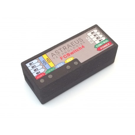
LED INDICATORS
The ATFCS4 includes 4 LEDs, with the following assignment:
- POWER LED (red): the device is powered at +5V.
- SIGNAL LED (green): a valid PWM signal is received through the CONTROL input.
- FC1 LED (blue): Flight Controller 1 is active and controlling the ESC outputs.
- FC2 LED (orange): Flight Controller 2 is active and controlling the ESC outputs.

SETUP TIPS
- The two Flight Controllers need to be connected in parallel to the RC receiver. The easiest way is using a single PPM signal, and connect the RC receiver PPM output to both Flight Controllers PPM input using a Y-type servo cable.
- It is highly recommended to perform a ground test, checking that with both controllers the roll, pitch and yaw behave correctly, in order to confirm that the ESCs are connected in the right order to both Flight Controllers outputs through the ATFCS4.
- In case of using two totally different Flight Controllers, with different arming procedures, make sure before taking off that both Flight Controllers are armed, performing both arming procedures, and switching between both Flight Controllers with the motors at low RPMs to confirm that both are armed.